Program Ports
Innovative solutions for your Panel Interface Connector (PIC) needs
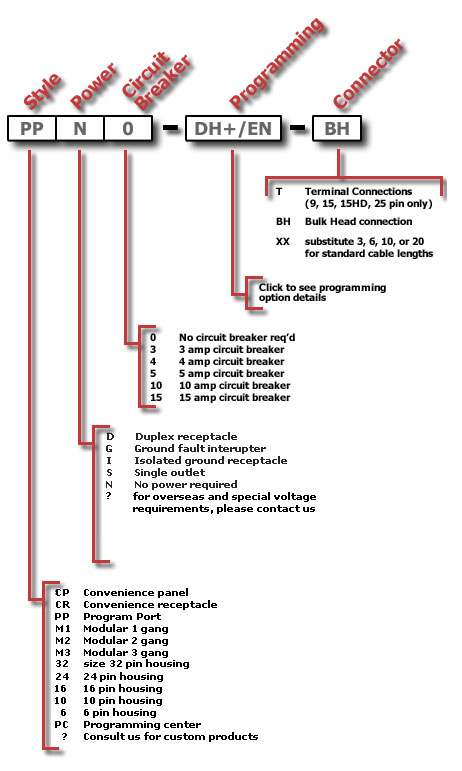
Program Port Style Solutions
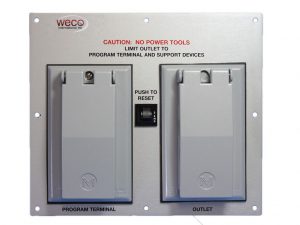
CP (Convenience Panel)
- Suitable for NEMA 12, where dust & oil mists are a concern
- Metal cover and mounting plate
- Requires less than 53 square inches of panel space
- Unit is TOUCH SAFE, by enclosing the duplex or GFI
- Comes with circuit breaker protection
- Attaches directly to the program port of most CNC or PLC processors, allowing programming access from outside of enclosure
- All mounting hardware provided
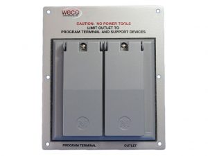
CR (Convenience Receptacle)
- Suitable for NEMA 12, where dust & oil mists are a concern
- Metal cover and mounting plate
- Requires less than 36 square inches of panel space
- Unit is TOUCH SAFE, by enclosing the duplex or GFI
- E-Z installation using standard 4″ square wireway knock-out
- Attaches directly to the program port of most CNC or PLC processors, allowing programming access from outside of enclosure
- All mounting hardware provided
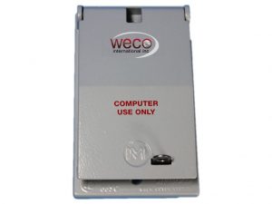
PP (Program Port)
- Suitable for NEMA 12, where dust & oil mists are a concern
- Metal cover construction
- Requires less than 12 square inches of panel space
- Can be ordered with with or without 115v power
- Attaches directly to the program port of most CNC or PLC processors, allowing programming access from outside of enclosure
- All mounting hardware provided
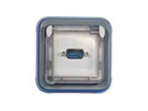
M1 (Modular 1 gang)
- Suitable for NEMA 4 & 12, where dust, oil mists, and wash downs are a concern
- Modular construction with interchangeable components and covers
- Plastic construction with Clear Cover
- Requires less than 12 square inches of panel space
- Can be ordered with 115/250v power
- Attaches directly to the program port of most CNC or PLC processors, allowing programming access from outside of enclosure
- All mounting hardware provided
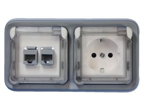
M2 (Modular 2 gang)
- Suitable for NEMA 4 & 12, where dust, oil mists, and wash downs are a concern
- Modular construction with interchangeable components and covers
- Plastic construction with Clear Cover
- Requires less than 21 square inches of panel space
- Can be ordered with 115/250v power
- Can be ordered with or without circuit breaker protection
- Attaches directly to the program port of most CNC or PLC processors, allowing programming access from outside of enclosure
- All mounting hardware provided
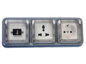
M3 (Modular 3 gang)
- Suitable for NEMA 4 & 12, where dust, oil mists, and wash downs are a concern
- Modular construction with interchangeable components and covers
- Plastic construction with Clear Cover
- Requires less than 31 square inches of panel space
- Can be ordered with 115/250v power
- Can be ordered with or without circuit breaker protection
- Attaches directly to the program port of most CNC or PLC processors, allowing programming access from outside of enclosure
- All mounting hardware provided
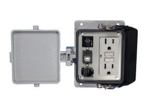
32 (size 32 pin housing)
- Suitable for NEMA 4, where wash downs are a concern
- Metal cover construction
- Requires less than 18 square inches of panel space
- Can be ordered with or without 115V power
- Attaches directly to the program port of most CNC or PLC processors, allowing programming access from outside of enclosure
- All mounting hardware provided
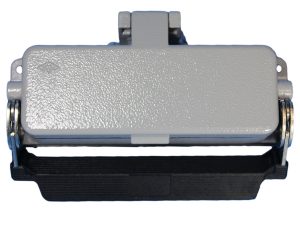
24 (size 24 pin housing)
- Suitable for NEMA 4, where wash downs are a concern
- Metal cover construction
- Requires less than 14 square inches of panel space
- Can be ordered with or without 115V power
- Attaches directly to the program port of most CNC or PLC processors, allowing programming access from outside of enclosure
- All mounting hardware provided
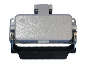
16 (Size 16 Pin Housing)
- Suitable for NEMA 4, where wash downs are a concern
- Metal cover construction
- Requires less than 18 square inches of panel space
- Can be ordered with or without 115V power
- Attaches directly to the program port of most CNC or PLC processors, allowing programming access from outside of enclosure
- All mounting hardware provided
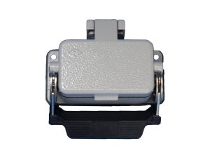
10 (Size 10 Pin Housing)
- Suitable for NEMA 4, where wash downs are a concern
- Metal cover construction
- Requires less than 10 square inches of panel space
- Attaches directly to the program port of most CNC or PLC processors, allowing programming access from outside of enclosure
- All mounting hardware provided
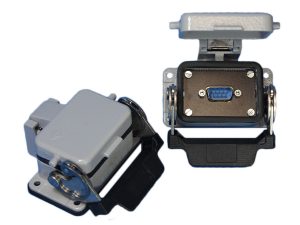
6 (Size 6 Pin Housing)
- Suitable for NEMA 4, where wash downs are a concern
- Metal cover construction
- Requires less than 18 square inches of panel space
- Can be ordered with or without 115V power
- Attaches directly to the program port of most CNC or PLC processors, allowing programming access from outside of enclosure
- All mounting hardware provided
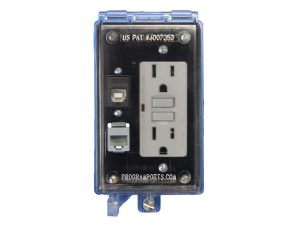
PC (Programming Center)
- Suitable for NEMA 4, where wash downs are a concern
- U.S. PAT#6,007,353
- Polycarbonate construction
- Requires less than 18 square inches of panel space
- Can be ordered with or without 115V power
- Attaches directly to the program port of most CNC or PLC processors, allowing programming access from outside of enclosure
- All mounting hardware provided
- Requires hand tool for opening cover

Special (Custom Products)
Since there are so many possible configurations that Program Parts can manufacture, please contact us and we’ll help you work through the particular requirements that you are in need of.
Power Ports Power Options
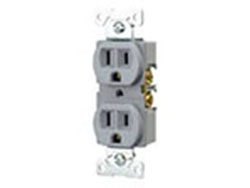
D (Duplex Outlet)
15 amp 110 volt
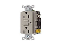
G (Ground fault interrupter)
Ground fault interrupter
15 amp 110 volt
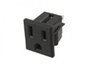
S (Single Outlet)
Single Outlet
15 amp 110 volt
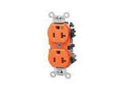
I (Isolated Ground Duplex Receptacle)
Isolated Ground Duplex Receptacle
15 amp 110 volt
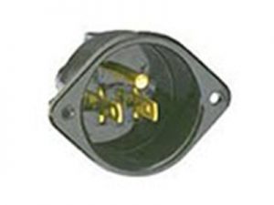
M (Male 110v Outlet)
Male North America outlet.
Ideal for powering remote enclosures by attaching extension cord.
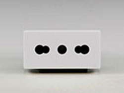
Overseas & Universal Outlets
There are a variety of outlets available for overseas and also universal outlets.
Argentina
10 amp 250 volt outlet
IRAM 1073
Australia and New Zealand
10 amp 250 volt outlet
China
10 amp 250 volt outlet
European
16 amp 250v European CEE 7 Schuko outlet
French Receptacle
16 amp 250 volt
Italy & Chile Outlet
10A-250V
Italy & Chile Multi-Outlet CEI 16/VII
South Africa, India & old style UK Outlet
16A-250V & 5A-250 S. Africa, India and old style United Kingdom
Multi-Outlet
Switzerland Outlet
10 amp 250v outlet type SEV 1011
type 13 for damp locations
Xtra Universal Outlet
Accepts; North America: NEMA 1-15P, 5-15P, 6-15P, 5-20P, 6-20P
United Kingdom: UK-13P, UK3-5
Japan: JA1-15P
European: EU1-16P (NON-GROUNDING)
Australia: AU1-10P, AU2-15P
China: CH1-10P
Argentina: AR1-10P
Europlug: 4.0 & 4.8 mm pins
Program Ports Programming Options
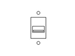
USBA
Connects directly to the Universal Serial Buss using a type A connector.
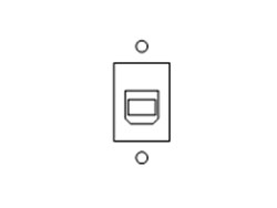
USBB
Connects directly to the Universal Serial Buss using a type B connector.
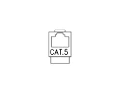
CAT5E
Connects directly to the communication port of any EtherNet 10 base T using a CAT5 connector.
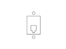
RJ
Connects directly to a RJ12 (6×6) or RJ11 (6×4).
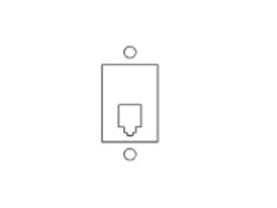
RJ7
Connects directly to a RJ7 (4×4 handset).
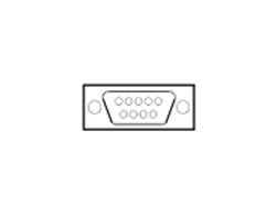
F9 / M9
Connects directly to a 9 pin
“D” shell connector.
F – Female under cover,
male at end of cable.
M – Male under cover,
female at end of cable.
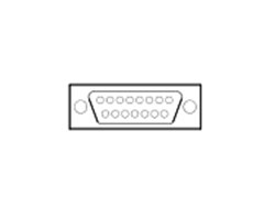
F15 / M15
Connects directly to a 15 pin
“D” shell connector.
F – Female under cover,
male at end of cable.
M – Male under cover,
female at end of cable.
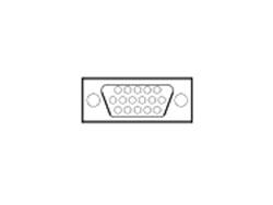
F15HD / M15HD
Connects directly to a 15 pin High Density “D” shell connector.
F – Female under cover,
male at end of cable.
M – Male under cover,
female at end of cable.
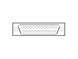
F37 / M37
Connects directly to a 37 pin
“D” shell connector.
F – Female under cover,
male at end of cable.
M – Male under cover,
female at end of cable.
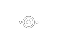
F6MD
Connects directly to a female 6 pin mini-DIN connector.
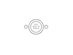
F8MD
Connects directly to a female 8 pin mini-DIN connector.
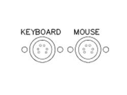
KM
Connects directly to two female 6 pin mini-DIN connectors allowing access for a keyboard and mouse connection.
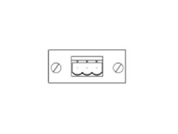
3P
Connects directly to the 3 pin connector similar to the KXT card, remote I/O or the DH+ channels having terminal connections.
(NO CABLE INCLUDED)
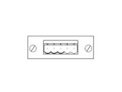
DN
Connects directly to the DeviceNet port using a 5 pin inline connector having terminal connections.
(NO CABLE INCLUDED)
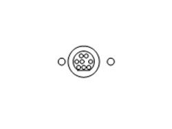
ML
Connects directly to the programming port of any MicroLogix™ family processor using a special keyed 8 pin connector.
(6 ft. cable only)
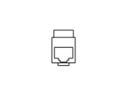
CN
Connects directly to the communication port of the ControlNet™ using a shielded
CAT5 connector.
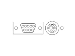
DH+
Connects directly to the Data Hwy. Plus network via a female 9 pin or a female 8 pin mini-din with terminal connections labeled 1, SH,2.
(NO CABLE INCLUDED)

DH8
Connects directly to the Data Hwy. Plus network via a female 8 pin mini-DIN with terminal connections labeled
1, SH,2.
(NO CABLE INCLUDED)
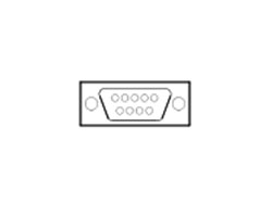
DH9
Connects directly to the Data Hwy. Plus network and is accessed by a 9 pin female “D” shell connector with terminal connections labeled 1, SH,2.
(NO CABLE INCLUDED)

OTHER CONFIGURATIONS
There are many possible configurations that can be manufactured. Contact us for the particular requirements that you are in need of.
Program Ports Connector Options
The following connection options to the unit are available:
| T – | a terminal strip is mounted on the back of the unit for point to point Terminal connections. (available for 9, 15, 15HD & 25 pin connectors only) |
| BH – | a pass thru bulk head style connector is used for easily connecting and disconnecting cables to and from unit. |
| XX – | Within the part number substitute the standard cable lengths of 3, 6, 10, or 20 (in feet). The end of this cable will have a connection that is the opposite sex from that of the specified connection. |
Prefix and suffix options: | |
| F – | indicates a Female connector under cover and a male connector at end of cable. |
| M – | indicates a Male connector under cover and a female connector at end of cable. |
| Note: | If same gender connector is required on both ends, specify gender type in front & behind desired pin size. Example: M9M-BH (Male 9 pin to a Male Bulk Head connector) |
Looking for the rest of the pieces?
WECO engineers are trained to help you put the pieces together to form your infrared heating solution. WECO designs custom ovens for products as small as contact lenses and as big as swimming pools.
Contact us today to discuss your project with our engineers.


